
Fiber Optic Splicing and Testing: The Backbone of Modern High-Speed Infrastructure
Introduction
In an era dominated by cloud computing, global digitalization, real-time data streaming, and ubiquitous internet connectivity, the underlying physical infrastructure determines the true speed and reliability of modern enterprise networks. At the core of this infrastructure lies fiber optic technology, which uses light signals to transmit vast amounts of data across immense distances with minimal latency. However, a fiber optic network is only as strong as its connections. Designing, deploying, and maintaining high-capacity optical networks requires flawless execution in two primary areas: splicing and testing. For leading engineering firms like Dam IT Solutions LLC, mastering these techniques ensures that enterprise clients benefit from optimal throughput, zero downtime, and a highly scalable digital foundation.
THE ART AND SCIENCE OF FIBER OPTIC SPLICING
Fiber optic splicing is the process of permanently joining two or more optical fibers together to form a continuous optical waveguide. Splicing is deployed during network expansions, when executing long-distance cable runs that exceed manufacturing lengths, or when repairing severed links resulting from construction accidents or environmental wear. There are two primary methodologies used to join optical fibers: Fusion Splicing and Mechanical Splicing.
1. Fusion Splicing: The Industry Gold Standard
Fusion splicing utilizes an automated high-precision machine that uses an electric arc to melt or fuse the glass ends of two fibers together. The objective is to combine the two cores so perfectly that the light passing through suffers virtually no scattering, reflection, or loss. Because fusion splicing creates a seamless, continuous glass path, it yields the lowest possible attenuation (insertion loss), typically less than 0.02dB per splice. This makes it the preferred choice for high-speed telecom networks, long-haul data paths, and complex enterprise data centers engineered by Dam IT Solutions LLC.
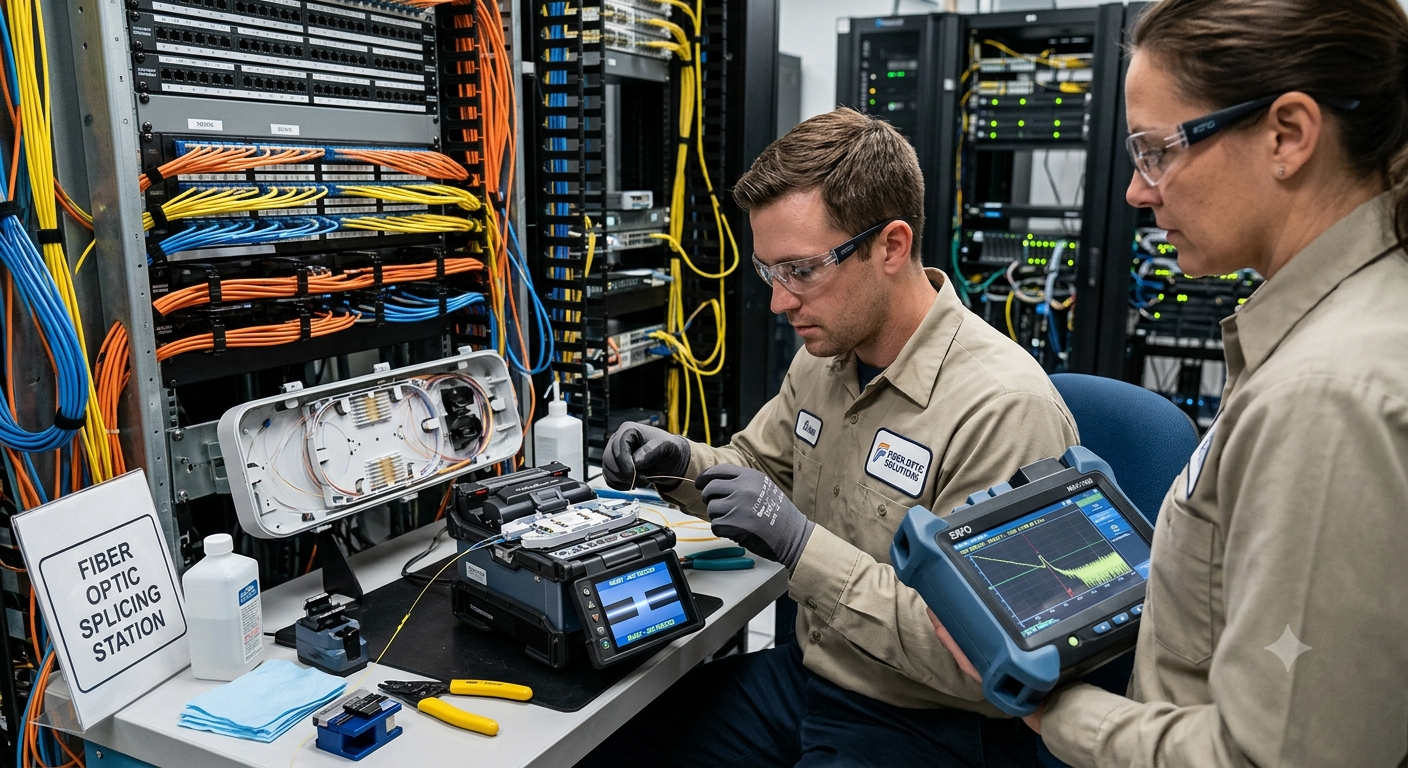
The fusion splicing process involves several critical, sequence-specific steps:
Stripping: The protective polymer coatings around the optical glass must be carefully stripped away using specialized mechanical strippers to expose the bare outer cladding.
Cleaning: The exposed bare glass must be thoroughly cleaned using 99% pure isopropyl alcohol and lint-free wipes to remove any microscopic dust particles, oil, or debris.
Cleaving: Using a precision fiber cleaver, the technician cuts the fiber to achieve a perfectly flat, perpendicular end-face (ideally a 90-degree angle). A poor cleave angle is the primary cause of high-loss fusion splices.
Alignment and Fusing: The fibers are placed into the fusion splicer, where automated cameras align the cores. The machine then delivers a brief electric arc to melt and fuse the tips together.
Protection: A heat-shrink sleeve with a strength member is slid over the bare splice zone and baked in a small built-in oven to provide structural integrity and protect the glass from moisture.
2. Mechanical Splicing: The Quick-Fix Alternative
Unlike fusion splicing, mechanical splicing does not melt the glass fibers together. Instead, it utilizes a small mechanical alignment fixture containing an internal index-matching gel that shares a similar refractive index to the glass core. The two prepared fiber ends are aligned inside the sleeve, and integrated clamps lock them in place. Mechanical splices exhibit higher insertion loss (typically between 0.1dB and 0.5dB) and are more susceptible to ambient temperature swings and aging. Therefore, teams like Dam IT Solutions LLC primarily reserve mechanical splicing for quick emergency restorations or temporary laboratory setups rather than permanent, mission-critical infrastructure deployments.
COMPREHENSIVE TESTING AND VERIFICATION PROCEDURES
Once the physical splicing phase is concluded, verifying the integrity of the network is paramount. Even a microscopic misalignment or an invisible crack inside a protective sleeve can degrade the performance of an entire network segment. Testing confirms that the power margins meet design parameters and provides a baseline for future troubleshooting. Elite technical integrators like Dam IT Solutions LLC execute tier-structured verification routines to guarantee compliance with international standards.
1. End-Face Inspection: Tier 1 Visual Validation
Before any light is introduced into the system, the fiber connectors and endpoints must undergo visual inspection. Using specialized video microscopes equipped with automated pass/fail software conforming to IEC 61300-3-35 standards, technicians check for dirt, scratches, pits, or oils. Connecting a contaminated fiber can permanently damage the optics of expensive transmission gear, making visual cleanliness the first line of defense.
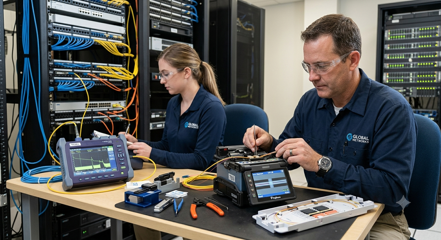
2. Optical Loss Testing (OLTS): Measuring Total Insertion Loss
Optical Loss Testing (commonly referred to as Tier 1 certification) measures the total amount of light lost across a fiber link from one end to the other. Utilizing a stable Light Source (OLS) at one end and an Optical Power Meter (OPM) at the opposite end, the test determines whether the overall link budget falls within the acceptable parameters calculated during the network design phase. OLTS provides a definitive pass or fail status regarding overall power delivery but does not isolate specific issues along the path.
3. Optical Time-Domain Reflectometry (OTDR): Tier 2 Advanced Diagnostics
For complex networks, long distances, or links containing multiple spliced segments, Tier 2 testing using an Optical Time-Domain Reflectometer (OTDR) is vital. The OTDR injects a series of high-power optical pulses into the fiber and analyzes the light that is reflected and backscattered back to the instrument. By plotting this data on a trace graph, the OTDR gives technicians a highly accurate visual map of the entire cable run.
An OTDR enables engineering teams at Dam IT Solutions LLC to pinpoint:
The precise location and specific insertion loss (in dB) of every single fusion or mechanical splice.
The performance, reflectance, and health of intermediate patch panels and end connectors.
The exact location of macrobends, cable stress points, or unexpected structural breaks.
The total physical length of the fiber optic cable run.
Conclusion
The reliability of modern telecommunications rests heavily on the meticulous execution of fiber optic splicing and precision testing. While cutting-edge fusion splicers and intelligent OTDR diagnostic units have streamlined field workflows, the accuracy of the final deployment still depends entirely on technical expertise and adherence to rigorous quality standards. Partnering with a proven technology specialist like Dam IT Solutions LLC ensures that your fiber optic infrastructure is built with the lowest possible insertion losses, verified with absolute precision, and engineered to support the next generation of digital bandwidth demands with complete stability.
